Site Plan Drawing Showing Contours
iii.6: Drawing Contour Lines and Topographic Profiles
- Page ID
- 5473
Overview
Constructing a topographic map by drawing in contours can exist easily done if a person remembers the following rules regarding contour lines:
- Profile lines represent lines connecting points of equal acme to a higher place sea level
- Contour lines never cross, split, or die off
- Profile intervals must be obeyed, therefore the contour line elevations can only be multiples of the contour interval
- Contour lines brand a "five" design as they cross streams and rivers, and the "v" always points towards the upstream management.
Equally you draw a contour line on a map you will find that the elevations on one side of your line will be lower elevations, and elevations on the other side of your line will exist higher elevations. In one case your contour lines are drawn, you volition discover that you had to draw some lines closer together in some areas and wider apart in other areas and that you may have even enclosed an area by cartoon a profile line in a round pattern. These circular patterns signal hilltops, similar in the diagram below (Figure 3.6). To illustrate what these hills look like in contour (or, how they would wait if y'all saw them while standing on the footing and looking at them from a distance), you can describe what is known as a topographic contour. Essentially a topographic contour is a side image of a topographic map, just the prototype is but a representation of the area shown on the line on the topographic map (line A-B on Figure 3.6).
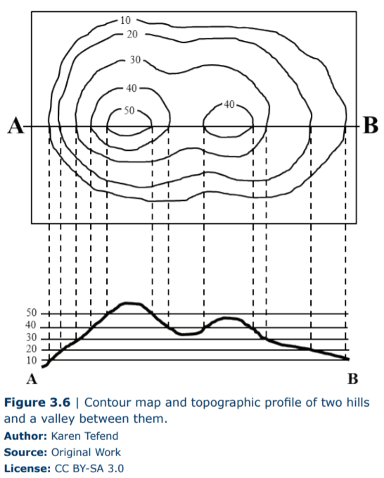
To construct a profile, you lot demand graph paper, a ruler, and a pencil. You desire to accept the y-axis of the graph paper represent the elevations of the contour lines that intersect your drawn line (line A-B in this case). By using a ruler, you lot can transfer these tiptop points from your topographic map straight down onto your graph paper such as shown in Figure three.6. Be sure to only plot those elevations that are at the intersection of the contour line with line A-B. Once your points are plotted on the graph newspaper, y'all simply connect the dots. As a rule, hilltops will be slightly rounded to prove a slight increase in elevation to represent the crest of the colina, simply be careful not to depict the hilltop besides high on your graph paper. For example, the beginning hill on the left has a top profile line of 50ft. Because in that location isn't a 60ft contour line on this hilltop, we know that the hill'due south highest point (the crest) is some elevation between 50 and 60ft.
When connecting the points on your graph newspaper in the area between the two hills in Effigy 3.half-dozen, yous again want to circular out the expanse to represent the base of your valley between the hills, but be careful non to make the valley floor too deep, every bit co-ordinate to the topographic map the elevation is below 40ft, merely non as low every bit 30ft.
If you lot examine the graph showing the topographic contour in Figure three.vi, tin y'all imagine what would happen to your contour if we inverse the spacing for elevations on the y-axis? When the vertical dimension of your graph is different from the horizontal dimension on your map, you may terminate up with a graph that shows a vertical exaggeration and the features of the World represented by your topographic profile may be deformed such as in Figure iii.7.
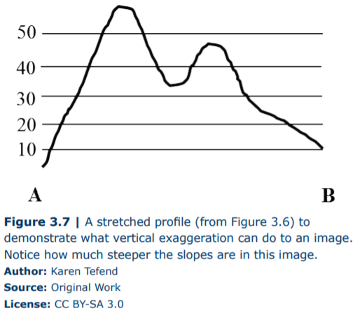
Sometimes vertical exaggeration is desired but, in some cases, you lot may not want it. To avoid having your profile distorted so that it accurately conveys what the surface of the Earth really looks similar in profile, y'all will desire both the vertical and horizontal scales to match. For case, if your map scale is 1 inch = 50 ft, then one inch on your graph'southward y-centrality should simply correspond 50ft of elevation. If the topographic map in Figure three.half dozen has a fractional calibration of 1:12,000 so 1 inch is equal to 12,000 inches or 1000ft; this 1inch = 1000ft equivalency is for the horizontal calibration. When we hold a ruler to the y-axis of the topographic profile in Effigy 3.6, we see that 0.5 inches = 50ft, which means one inch = 100ft on the vertical scale. To calculate the vertical exaggeration in the topographic profile shown in Effigy 3.half dozen we divide the horizontal scale past the vertical scale: (\(\frac{\frac{chiliad\;ft}{1\;inch})}{(\frac{100\;ft}{inch}}) = 10\). Therefore the topographic profile in Figure 3.half dozen represents a profile of the map surface (along the A-B line) that has been vertically exaggerated past 10 times (10X).
Answers to Practice Lab Exercises, Parts A and B
- 76°15'00" West longitude
- 43°00'00" North latitude
- 2000 ft
- 1 ft = 24,000 ft, and 24,000 ft x (\(\frac{ane\;km}{3280\;ft}\)) = 7.32 km
- Southward
weingartnerfrivinse.blogspot.com
Source: https://geo.libretexts.org/Learning_Objects/Laboratory/Book%3A_Laboratory_Manual_For_Introductory_Geology_(Deline_Harris_and_Tefend)/03%3A_Topographic_Maps/3.6%3A_Drawing_Contour_Lines_and_Topographic_Profiles
0 Response to "Site Plan Drawing Showing Contours"
Postar um comentário